When Opened The Interlock Circuit
Interlock circuit diagram circled vacuum individually sections described text figure detail Electrical interlock circuit diagram Interlock circuit
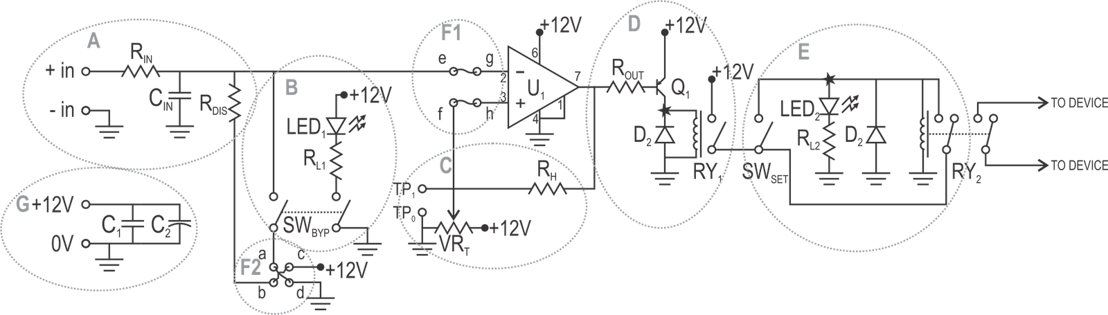
Interlock schematic. All valves are normally closed, relay pass current
What is electrical interlocking Interlock faqs Interlock temperature schematic bart sigurdsson technical reference
Interlock circuit
What is electrical interlocking power diagramsConfigurations interlock Interlock troublesRepository-circuits page 585 :: next.gr.
Interlock electricalWhat is electrical interlocking? Switches safety locking interlock gate magnetic rfid automationdirect library non contactInterlock logic diagram.

Relay interlocking relays
Interlock circuit diagramDoor interlock system circuit diagram Safe start interlock wiring diagram questionInterlock schematic. all valves are normally closed, relay pass current.
Electronic – multi-relay interlock circuit/control – valuable tech notesStop start circuit emergency basic interlock mean do testing systems those categories really ure fig 2010 What is interlocking ?Interlock diagram. it uses two units to protect the module inside the.

Interlock interlocking contactor parallel connection
Basic interlocking of electrical circuitCircuit electrical interlocking power electricaltechnology diagram Circuit analysisInterlock electrical-exam.
Mechanical interlockFaqs: what is an "external interlock"? why should i use it? Solved: in the circuit shown below, the switch has been op...Interlock circuit 회로실습.

Interlock breakers breaker benshaw frame interlocks
Interlocking circuitPatent us8824113 Interlock relay schematic valves normally current controlInterlock control.
Temperature interlockSafety interlock circuit for vacuum systems Interlock architecturesElectrical interlock circuit diagram.

(a) rf interlock circuit.
Two interlock configurations [1].Locking safety interlock switches Interlocking circuits(b) rf interlock circuit..
Interlocking electrical control power diagram system circuit motor electronic diagrams simple forward connection wayInterlock module chamber arrangement How to interlocking in electrical system.

(a) RF interlock circuit. | Download Scientific Diagram

switches - Is this design feasible? Door-open warning light circuit

Interlock schematic. All valves are normally closed, relay pass current

What is Interlocking ? | Interlocking circuit Connection between two

(b) RF interlock circuit. | Download Scientific Diagram

Temperature Interlock

What is Electrical Interlocking? - Power and Control Diagrams